Saturday, October 13, 2018

Capacitor Voltage-Current Relations

Purpose: In this lab, we will measure the voltage and current across a capacitor to see the relationship between them.
Pre-lab:
By measuring the voltage across the capacitor, we can easily calculate the current across it by using: Ic=Vr/R since resistor and capacitor are connected in series, so they have the same current pass through.


 Triangular of Vr and Vc
 Sinusoidal of Vr and Vc
 Picture of our circuit.
Triangular of Vr and Vc


Saturday, October 6, 2018

Summing Amplifier

Purpose:
Pre-lab: Calculate Vout based on 2 Vins (Va and Vb) with Vb=1, Va=-4,-2,-1,0,1,2,3 and 5V.
R1=1.77kΩ, R2=1.19kΩ, R3=1.29kΩ


At 5V, it reaches saturation because value of Vexp vs Vtheo is off. 

Inverting Voltage Amplifier

Purpose:
Pre-lab: Based on the circuit constructed below:

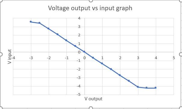
We changed the value of Vin from -3V to 4V with the increment of 0.5V, and find Vout. Since this is an inverting voltage amplifier, we have value voltages from -3V to 3V symmetrical with. Vout on the left column is Vout eperimental, and on the right column is Vout theoretical. 
When it reaches saturation, we will not get the Vout experimental the same as Vout theoretical. Vcc+ and Vcc- are controlling the max value of V output in Op-amp.

Here are pictures of out circuit.

Graph of Vout vs Vin
In this graph also represents exactly the saturation and linear region as we discussed in class.

Saturday, September 22, 2018

Thevenin's Theorem

Purpose: 
Pre-lab: Based on Thevenin's Theorem, we calculate Vth, Rth for the circuit belove
Based on the actual value of our resistors, we found Voc=0.437V, Rth= 7.4k Ω. Then we calculated I=3.6116 x 10^-5 A, Vload(4.7kΩ)=0.1697V

When we constructed the circuit and measured value of Rth =7.33kΩ, Vth=0.1707V 

 This is the value of Vload when we connected Rload with Rth, Vload = 0.1781V
In conclusion, there is only a small difference (4.7%) in voltage of Rload (0.1781V vs 0.1697V) when constructing a circuit with a bunch of resistors and the circuit with Rth connect with Rload in series.

Saturday, September 15, 2018

Dusk-to-Dawn-Light

Purpose:


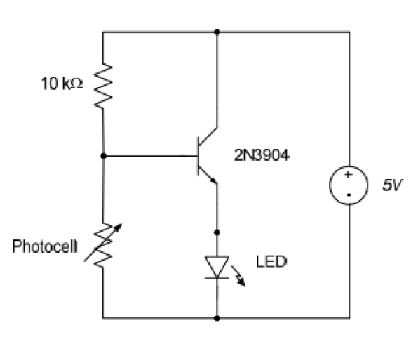
Pre-lab: We construct a circuit belove.
The picture of our circuit constructed with photocell, resistor, power sources, and transistor. 


This picture shows the value of the current when the photocell is not covered 
This picture shows the value of the current when the photocell is covered 
Here is the video, but we cannot clearly see between low and high light level since we turned of the light in the room. If we left the light in the room on, we could see clearly that the LED will brighter when we cover the photocell, and vice versa. 


Mesh Analysis


Purpose: Construct the circuit above and using mesh method to find V1 and V2 in pre-lab, and using either DMM or Digital analog to find experimental values of V1 and V2.
Pre-lab: Using mesh method to find V1 and V2.

Through experiment using DMM, we measured V1=4.40V, V2=2.42V

%Error of V1 = (|4.40-4.43| / 4.43)*100 = 0.68%
%Error of V2 = (|2.42-2.43| / 2.43)*100 = 0.42%
The percent error in this and previous lab is very small because the value of resistors are nothing compare to the internal resistor of DMM. 

-------------------------

Purpose: In the same manner of the previous lab, we use mesh method to determine the value of V1 in the circuit above.
Pre-lab: Calculating V1, I1

By using DMM, we measure voltage across 10k resistor and V1 are 3.20V, 4.98V (also equal to 5V voltage source in parallel with it.)

% Error of voltage across 10K resistor: (|3.20-3.21|/3.21)*100=0.31%
%Error of V1: (|4.98-5.00|/5.00)*100=0.4 %

--------

Purpose: In this lab, we also calculate and simulate the circuit to find the value of V1 and I1. 
Pre-lab: 
We used the mesh method to solve this problem. The actual value of resistors being used are 1.3k,  4.7k, 6.6k, and 21.7k. We calculated I1 = 0.288A, I2 = 0.927A, and I3 = 0.109A from the loop equations.  From values just found, we calculated the voltage goes through 1.3k and 21.7k resistors are 0.374V , 2.35V.
These values belove are what we got by using DMM to measure voltage across 1.3k and 21.7k resistor.

Percent error of current I1 = (|0.282-0.288)/0.288)x100 = 2.08%
Percent error of voltage V1= (|2.45-2.35|)/2.45)x 100 = 4.08%
There is a small percent error because of the value of resistors are too small compared to the internal resistor of DMM.

Thursday, September 6, 2018

Nodal Analysis

Purpose: 
Pre-lab: Use nodes method to find V1 and I1 in the circuit above:

As we found: I1 = 0.321 mA, V1= 5V since it is parallel with 5V source. 
During the experiment, we found V1= 4.98V, and I1= 0.320mA (I1, in this case, is calculated using V of DMM divides by 10k resistor.


Percent error of V1 = (| 4.98 - 5.00| / 5) x 100 = 10%
Percent error of I1 = (|0.320 - 0.321| / 0.321) x 100 = 0.31%
The reason for the high percent error of V1 because of the actual value of the resistor being used was 6.6k instead of 6.8k. There will be also a small error in current because of the value of the resistor was too small compared to the internal resistance of DMM.
-----------
Purpose: In this lab, we also calculate and simulate the circuit to find the value of V1 and I1. 

Pre-lab: 
We used the mesh method to solve this problem. The actual value of resistors being used are 1.3k,  4.7k, 6.6k, and 21.7k. We calculated I1 = 0.288A, I2 = 0.927A, and I3 = 0.109A from the loop equations.  From values just found, we calculated the voltage goes through 1.3k and 21.7k resistors are 0.374V , 2.35V.
These values belove are what we got by using DMM to measure voltage across 1.3k and 21.7k resistor.

Percent error of current I1 = (|0.282-0.288)/0.288)x100 = 2.08%
Percent error of voltage V1= (|2.45-2.35|)/2.45)x 100 = 4.08%
There is a small percent error because of the value of resistors are too small compared to the internal resistor of DMM.